1963-1982 Front Coilover Instructions

Tools Needed
• 9/16”, 5/8”, 11/16” & 3⁄4” Wrench & Socket
• Pry Bar or Long Screwdriver
• Rubber Mallet
• 3/8” Allen Head Socket/T-handle • Torque Wrench
• (oiled)=Anti-seize
PARTS LIST
- (2) Upper control arms
- – ball joint is offset towards the firewall
- (2) Lower conrol arms
- – sway bar tab towards front of car
- (2) 1/2-20×2.5 bolts with reducing washer
- (2) aluminum clamps with 7/16 bolts
- (2) shock assemblies
- – upper clevis pre-installed
- (1) 1.125” Front sway bar
- (2) rod end sway bar endlinks
- – installed on lower control arms
- (2) 1.125” frame mount bushings
- (2) spanner wrenches
Once you have the old arms removed from the car you can start installing the tubular arms on your Corvette.
Installing Van Steel Tubular Lower A-Arms


First, start with the lower a-arms. The flat part of the shaft goes against the frame. There is a bolt that comes in the lower control arm cross shaft (Figure 1). This bolt goes toward the rear of the car. There is a top hat style reducing washer. Remove the bolt and washer from the arm and drop it through the frame bracket. The top hat part of the washer should face down. This washer is designed to reduce the gap of the OE hole to accommodate the 1⁄2” bolt supplied.
Moving toward the front side of the arm you can install the aluminum cradle bracket that is supplied with the (Figure 2) 7/16-20-1.5” Allen head bolts and lock washers. You are to re-use your existing 2 hole plate that came on the car. You will need a 3/8” Allen head socket/wrench/T-handle to tighten these down. (Figure 3) Do not torque these yet as you should move to the rear bolt again and torque it 1st. Torque the rear bolt to 60 ft/ lbs. (oiled) and the front bolts to 40ft/lbs.
Installing Upper A-Arms


The ball joint is going to sit further back in the car than the OE upper a-arm. Shown in Figure 4 is a left front upper. Align the holes in the cross shaft to the alignment studs in the frame. (We recommend using a rubber mallet as these bolts can be tweaked a little bit and you may need to hit a stud forward or backward.) If the studs are out and you are installing new studs, slide the a-arm into po- sition and push the studs through the frame and through the cross shaft by hand until you get to the knurl of the stud. Place the 7/16” flat washers over the stud and thread the alignment nut onto the alignment stud and drive the studs into place so that they are seated. Once the studs are seated, tighten the alignment nuts. For starters, you can use a 1/16” shim on the front stud and a 1/16” + a 1/8” shim on the rear stud. Once you get the car aligned, the alignment shop will correctly place the correct size shims be- tween the frame and the cross shaft. Refer to the Alignment Spec Sheet at the end of the instruction packet.
Installing Coilover Shocks – top only


<- On top of the Coilover is a clevis mount. The mount will have 1 flat washer and a flange pinch nut. Remove the nut as the washer will stay on the top of the mount. (Figure 6)
Next, slide the shock into place. You may need to grind the threaded section of the bolt that goes through the shocks and/or use a die grinder to put a slot in the frame hole to clear the bolt.
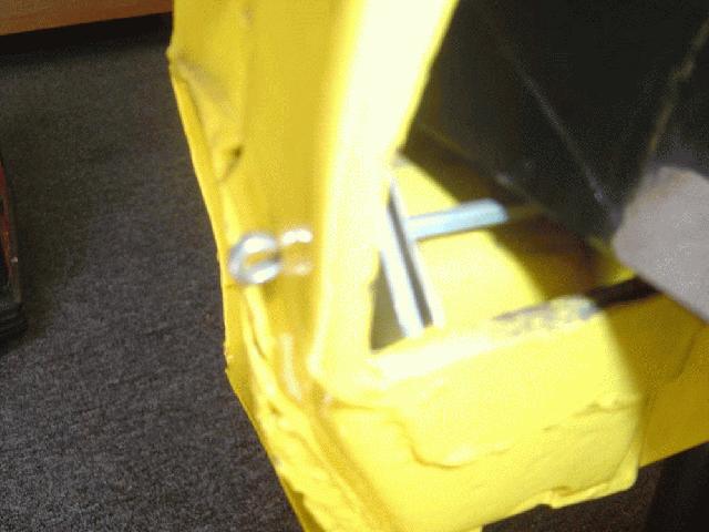
Once the shock is in place and the stud is through the OE shock hole, install the flange nut that you removed before you started the install and tighten so the stud engages the pinch nut. Make sure the head of the bolt (Figure 7) is facing the front of the car. You will need a pry bar or screwdriver to hold the upper clevis from rotating as you tighten the nyloc nut (Figure 8). Torque to 40 ft/lbs.
Installing Front Spindle Assembly


Install the lower ball joint on to the bearing assembly spindle and thread the nut on.
Next, place your floor jack under the lower a-arm with a block of wood. (Figure 9) Jack the arm up until you have clearance to insert the upper ball joint into the spindle. Once the stud of the upper ball joint is through the spindle, thread the nut on. ***PLEASE NOTE THE CAR MAY START TO LIFT OFF THE JACK STANDS/LIFT.
Once the front assembly is on you can refer to your assembly manual on how to install the rest of the steering parts (i.e., tie rod ends, center link etc).
Install Lower Shock Mount

On the lower a-arm, remove the 1⁄2” bolt and nut from the shock mount. Loosen the spring collar all the way down and make sure your valving is at zero. Now you can compress the shock to line up the shock mount hole with the bracket for the lower mount. Slide the 1⁄2” bolt through the hole and install the nut. We use a long bolt here because we like to get as much of the shank of the bolt through the shock as possible because it’s stronger. Torque to 50 ft/lbs. Retighten the spring collar up until it gets hard to tighten by hand. This should put the car just under factory ride height depending on the spring rate and weight of your Vette.
Setting Ride Height

Now that your system is installed minus your sway bar end links, you’ll need to adjust the springs to set your ride height. The system ships with the springs just hand tightened. This is typically a good starting point and should allow for around a 1” drop. If you want a closer to factory ride height, I’d go up on the collar 3/4”.
The shock shown to the left is just hand tightened and is our recommended lowest starting point.
When adjusting coilovers, make sure you disconnect at least one end link so the sway bar doesn’t hold up any ride height changes.
Sway Bar End Link Orientation

DO NOT install the front end links on the sway bar until the car is at the preferred ride height. At least one end link should be disconnected when adjusting ride height.
The 1 1/8” bar (which works well for all models using 215-225 width tires for C2 or 225-255 on C3s) uses rod ends for end links for better sway bar orientation when altering ride height. Figure 10 shows how the end link hardware should be oriented on the lower control arm.
The dip in the sway bar should dip down away from the radiator. The end links should mount to the inboard side of the sway bar to keep them as vertical as possible.
To set up the heim end, you must first have the car at ride height (ramps or drive on lift). Next choose your sway bar stiffness (two hole adjustable), the closest to the end of the bar will be the softer of the two settings. You’ll want to setup the end link to be as close to perpendicular to the ground as
you can. Once both end links are installed, you should be able to rotate the heim with minimal to no binding (by hand or with a wrench). Enjoy the upgraded handling of you Corvette!